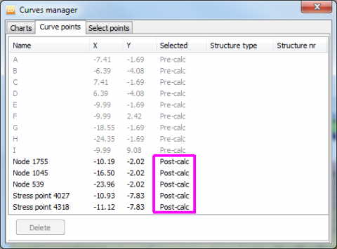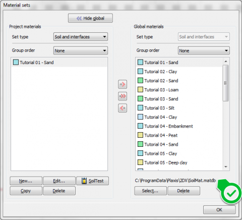

Material data sets from the projects database may be copied to the global database, for use in other projects. Material properties for soil, as well as for structural elements are entered in a project database.

Loads values can be changed in the “staged construction” mode and/or using load multipliers Point loads may be used at any geometry point, whereas distributed loads may be applied to any geometry line, not only limited to the geometry boundary. Two independent load systems can be used to apply point loads and distributed loads. A convenient option exists to use standard boundary conditions that apply in most cases. Prescribed displacements are special conditions that can be imposed on geometry lines to control the displacements of these lines. These conditions can be applied to geometry lines as well as to geometry points in x and y directions. Various methods have been implemented to analyse the deformations that occur as a result of various methods of tunnel construction.įixities are prescribed displacements equal to zero. Fully isoparametric elements are used to model the curved boundaries within the mesh. Plates and interfaces may be used to model the tunnel lining and the interaction with the surrounding soil.

The Plaxis program offers a convenient option to create circular and non-circular tunnels using arcs and lines. It is often convenient to combine these elements with interfaces to model the interaction with the surrounding soil. These elements can be simulated in Plaxis by the use of special tension elements. Geogrids (or geotextiles) are often used in practice for the construction of reinforced embankments or soil retaining structures. A special option exists for the analyses of pre-stressed ground anchors and excavation supports. The behaviour of these elements is defined using an axial stiffness and a maximum force. Values of interface friction angle and adhesion are generally not the same as the friction angle and cohesion of the surrounding soil.Įlastoplastic spring elements are used to model anchors and struts. For example, these elements may be used to simulate the thin zone of intensely shearing material at the contact between a tunnel lining and the surrounding soil. Joint elements are available to model soilstructure interaction. Hinges may be introduced to create joints where plate ends can rotate freely, or with rotation springs for connections that are neither pinned nor fully fixed. Plates with interfaces may be used to perform realistic analyses of geotechnical structures.Ī hinge is a connection that allows for a discontinuous rotation in the point of connection (joint). A plastic hinge may develop for elastoplastic plates, as soon as the ultimate moment is mobilised.

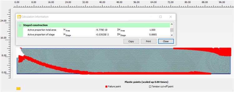
The behaviour of these elements is defined using a flexural rigidity, an axial stiffness and an ultimate bending moment. Special plate elements are used to model the bending of retaining walls, tunnel linings, shells, and other slender structures. Quadratic 6-node and 4th order 15-node triangular elements are available to model the deformations and stresses in the soil. The mesh may contain thousands of elements. Plaxis allows for fully automatic generation of unstructured finite element meshes with options for global and local mesh refinement. From this geometry model, a 2D finite element mesh is easily generated. The input of soil layers, structures, construction stages, loads and boundary conditions is based on convenient CAD drawing procedures, which allows for a detailed modelling of the geometry cross-section.


 0 kommentar(er)
